Learning Objectives
Learning Objectives
By the end of this section, you will be able to do the following:
- Explain wave behavior of light, including diffraction and interference, including the role of constructive and destructive interference in Young’s single-slit and double-slit experiments
- Perform calculations involving diffraction and interference, in particular the wavelength of light using data from a two-slit interference pattern
| diffraction | Huygens’s principle | monochromatic |
| wavefront |
Diffraction and Interference
Diffraction and Interference
We know that visible light is the type of electromagnetic wave to which our eyes responds. As we have seen previously, light obeys the equation
where m/s is the speed of light in vacuum, f is the frequency of the electromagnetic wave in Hz (or s–1), and is its wavelength in m. The range of visible wavelengths is approximately 380 to 750 nm. As is true for all waves, light travels in straight lines and acts like a ray when it interacts with objects several times as large as its wavelength. However, when it interacts with smaller objects, it displays its wave characteristics prominently. Interference is the identifying behavior of a wave.
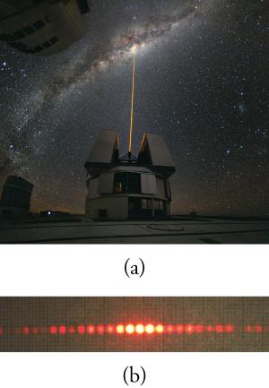
In Figure 17.2, both the ray and wave characteristics of light can be seen. The laser beam emitted by the observatory represents ray behavior, as it travels in a straight line. Passing a pure, one-wavelength beam through vertical slits with a width close to the wavelength of the beam reveals the wave character of light. Here we see the beam spreading out horizontally into a pattern of bright and dark regions that are caused by systematic constructive and destructive interference. As it is characteristic of wave behavior, interference is observed for water waves, sound waves, and light waves.
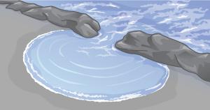
That interference is a characteristic of energy propagation by waves is demonstrated more convincingly by water waves. Figure 17.3 shows water waves passing through gaps between some rocks. You can easily see that the gaps are similar in width to the wavelength of the waves and that this causes an interference pattern as the waves pass beyond the gaps. A cross-section across the waves in the foreground would show the crests and troughs characteristic of an interference pattern.
Light has wave characteristics in various media as well as in a vacuum. When light goes from a vacuum to some medium, such as water, its speed and wavelength change, but its frequency, f, remains the same. The speed of light in a medium is , where n is its index of refraction. If you divide both sides of the equation by n, you get . Therefore, , where is the wavelength in a medium, and
where is the wavelength in vacuum and n is the medium’s index of refraction. It follows that the wavelength of light is smaller in any medium than it is in vacuum. In water, for example, which has n = 1.333, the range of visible wavelengths is (380 nm)/1.333 to (760 nm)/1.333, or 285–570 nm. Although wavelengths change while traveling from one medium to another, colors do not, since colors are associated with frequency.
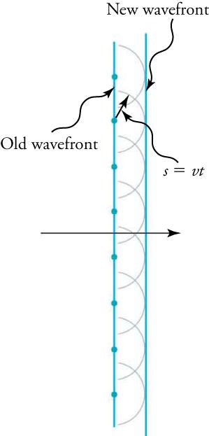
The Dutch scientist Christiaan Huygens (1629–1695) developed a useful technique for determining in detail how and where waves propagate. He used wavefronts, which are the points on a wave’s surface that share the same, constant phase (such as all the points that make up the crest of a water wave). Huygens’s principle states, “Every point on a wavefront is a source of wavelets that spread out in the forward direction at the same speed as the wave itself. The new wavefront is a line tangent to all of the wavelets.”
Figure 17.4 shows how Huygens’s principle is applied. A wavefront is the long edge that moves; for example, the crest or the trough. Each point on the wavefront emits a semicircular wave that moves at the propagation speed v. These are drawn later at a time, t, so that they have moved a distance . The new wavefront is a line tangent to the wavelets and is where the wave is located at time t. Huygens’s principle works for all types of waves, including water waves, sound waves, and light waves. It will be useful not only in describing how light waves propagate, but also in how they interfere.
What happens when a wave passes through an opening, such as light shining through an open door into a dark room? For light, you expect to see a sharp shadow of the doorway on the floor of the room, and you expect no light to bend around corners into other parts of the room. When sound passes through a door, you hear it everywhere in the room and, thus, you understand that sound spreads out when passing through such an opening. What is the difference between the behavior of sound waves and light waves in this case? The answer is that the wavelengths that make up the light are very short, so that the light acts like a ray. Sound has wavelengths on the order of the size of the door, and so it bends around corners.
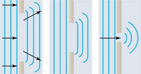
If light passes through smaller openings, often called slits, you can use Huygens’s principle to show that light bends as sound does (see Figure 17.5). The bending of a wave around the edges of an opening or an obstacle is called diffraction. Diffraction is a wave characteristic that occurs for all types of waves. If diffraction is observed for a phenomenon, it is evidence that the phenomenon is produced by waves. Thus, the horizontal diffraction of the laser beam after it passes through slits in Figure 17.2 is evidence that light has the properties of a wave.
Once again, water waves present a familiar example of a wave phenomenon that is easy to observe and understand, as shown in Figure 17.6.
Watch Physics
Single-Slit Interference
This video works through the math needed to predict diffraction patterns that are caused by single-slit interference.
Which values of m denote the location of destructive interference in a single-slit diffraction pattern?
- whole integers, excluding zero
- whole integers
- real numbers excluding zero
- real numbers
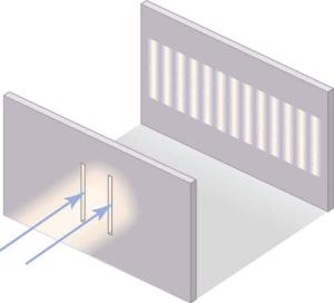
The fact that Huygens’s principle worked was not considered enough evidence to prove that light is a wave. People were also reluctant to accept light’s wave nature because it contradicted the ideas of Isaac Newton, who was still held in high esteem. The acceptance of the wave character of light came after 1801, when the English physicist and physician Thomas Young (1773–1829) did his now-classic double-slit experiment (see Figure 17.7).
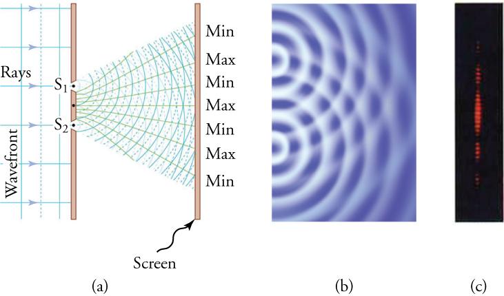
When light passes through narrow slits, it is diffracted into semicircular waves, as shown in Figure 17.8 (a). Pure constructive interference occurs where the waves line up crest to crest or trough to trough. Pure destructive interference occurs where they line up crest to trough. The light must fall on a screen and be scattered into our eyes for the pattern to be visible. An analogous pattern for water waves is shown in Figure 17.8 (b). Note that regions of constructive and destructive interference move out from the slits at well-defined angles to the original beam. Those angles depend on wavelength and the distance between the slits, as you will see below.
Virtual Physics
Wave Interference
This simulation demonstrates most of the wave phenomena discussed in this section. First, observe interference between two sources of electromagnetic radiation without adding slits. See how water waves, sound, and light all show interference patterns. Stay with light waves and use only one source. Create diffraction patterns with one slit and then with two. You may have to adjust slit width to see the pattern.
Visually compare the slit width to the wavelength. When do you get the best-defined diffraction pattern?
- when the slit width is larger than the wavelength
- when the slit width is smaller than the wavelength
- when the slit width is comparable to the wavelength
- when the slit width is infinite
Calculations Involving Diffraction and Interference
Calculations Involving Diffraction and Interference
The fact that the wavelength of light of one color, or monochromatic light, can be calculated from its two-slit diffraction pattern in Young’s experiments supports the conclusion that light has wave properties. To understand the basis of such calculations, consider how two waves travel from the slits to the screen. Each slit is a different distance from a given point on the screen. Thus different numbers of wavelengths fit into each path. Waves start out from the slits in phase (crest to crest), but they will end up out of phase (crest to trough) at the screen if the paths differ in length by half a wavelength, interfering destructively. If the paths differ by a whole wavelength, then the waves arrive in phase (crest to crest) at the screen, interfering constructively. More generally, if the paths taken by the two waves differ by any half-integral number of wavelengths , then destructive interference occurs. Similarly, if the paths taken by the two waves differ by any integral number of wavelengths , then constructive interference occurs.
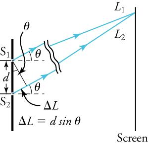
Figure 17.10 shows how to determine the path-length difference for waves traveling from two slits to a common point on a screen. If the screen is a large distance away compared with the distance between the slits, then the angle between the path and a line from the slits perpendicular to the screen (see the figure) is nearly the same for each path. That approximation and simple trigonometry show the length difference, , to be , where d is the distance between the slits,
To obtain constructive interference for a double slit, the path-length difference must be an integral multiple of the wavelength, or
Similarly, to obtain destructive interference for a double slit, the path-length difference must be a half-integral multiple of the wavelength, or
The number m is the order of the interference. For example, m = 4 is fourth-order interference.
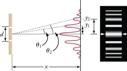
Figure 17.11 shows how the intensity of the bands of constructive interference decreases with increasing angle.
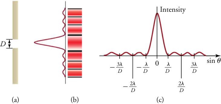
Light passing through a single slit forms a diffraction pattern somewhat different from that formed by double slits. Figure 17.12 shows a single-slit diffraction pattern. Note that the central maximum is larger than those on either side, and that the intensity decreases rapidly on either side.
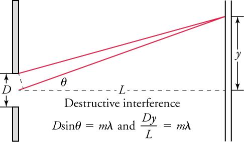
The analysis of single-slit diffraction is illustrated in Figure 17.13. Assuming the screen is very far away compared with the size of the slit, rays heading toward a common destination are nearly parallel. That approximation allows a series of trigonometric operations that result in the equations for the minima produced by destructive interference.
or
When rays travel straight ahead, they remain in phase and a central maximum is obtained. However, when rays travel at an angle relative to the original direction of the beam, each ray travels a different distance to the screen, and they can arrive in or out of phase. Thus, a ray from the center travels a distance farther than the ray from the top edge of the slit, they arrive out of phase, and they interfere destructively. Similarly, for every ray between the top and the center of the slit, there is a ray between the center and the bottom of the slit that travels a distance farther to the common point on the screen, and so interferes destructively. Symmetrically, there will be another minimum at the same angle below the direct ray.
Below we summarize the equations needed for the calculations to follow.
The speed of light in a vacuum, c, the wavelength of the light, , and its frequency, f, are related as follows.
The wavelength of light in a medium, , compared to its wavelength in a vacuum, , is given by
To calculate the positions of constructive interference for a double slit, the path-length difference must be an integral multiple, m, of the wavelength.
where d is the distance between the slits and is the angle between a line from the slits to the maximum and a line perpendicular to the barrier in which the slits are located. To calculate the positions of destructive interference for a double slit, the path-length difference must be a half-integral multiple of the wavelength:
For a single-slit diffraction pattern, the width of the slit, D, the distance of the first (m = 1) destructive interference minimum, y, the distance from the slit to the screen, L, and the wavelength, , are given by
Also, for single-slit diffraction,
where is the angle between a line from the slit to the minimum and a line perpendicular to the screen, and m is the order of the minimum.
Worked Example
Two-Slit Interference
Suppose you pass light from a He-Ne laser through two slits separated by 0.0100 mm, and you find that the third bright line on a screen is formed at an angle of 10.95º relative to the incident beam. What is the wavelength of the light?
STRATEGY
The third bright line is due to third-order constructive interference, which means that m = 3. You are given d = 0.0100 mm and = 10.95º. The wavelength can thus be found using the equation for constructive interference.
The equation is . Solving for the wavelength, , gives
Substituting known values yields
To three digits, 633 nm is the wavelength of light emitted by the common He-Ne laser. Not by coincidence, this red color is similar to that emitted by neon lights. More important, however, is the fact that interference patterns can be used to measure wavelength. Young did that for visible wavelengths. His analytical technique is still widely used to measure electromagnetic spectra. For a given order, the angle for constructive interference increases with , so spectra (measurements of intensity versus wavelength) can be obtained.
Worked Example
Single-Slit Diffraction
Visible light of wavelength 550 nm falls on a single slit and produces its second diffraction minimum at an angle of 45.0° relative to the incident direction of the light. What is the width of the slit?
STRATEGY
From the given information, and assuming the screen is far away from the slit, you can use the equation to find D.
Quantities given are = 550 nm, m = 2, and = 45.0°. Solving the equation for D and substituting known values gives
You see that the slit is narrow (it is only a few times greater than the wavelength of light). That is consistent with the fact that light must interact with an object comparable in size to its wavelength in order to exhibit significant wave effects, such as this single-slit diffraction pattern.
Practice Problems
Practice Problems
What is the width of a single slit through which 610-nm orange light passes to form a first diffraction minimum at an angle of 30.0°?
- 0.863 µm
- 0.704 µm
- 0.610 µm
- 1.22 µm
Check Your Understanding
Check Your Understanding
- The wavelength first decreases and then increases.
- The wavelength first increases and then decreases.
- The wavelength increases.
- The wavelength decreases.
- This is a diffraction effect. Your whole body acts as the origin for a new wavefront.
- This is a diffraction effect. Every point on the edge of your shadow acts as the origin for a new wavefront.
- This is a refraction effect. Your whole body acts as the origin for a new wavefront.
- This is a refraction effect. Every point on the edge of your shadow acts as the origin for a new wavefront.
- The wavelength first decreases and then increases.
- The wavelength first increases and then decreases.
- The wavelength increases.
- The wavelength decreases.
