Learning Objectives
Learning Objectives
By the end of this section, you will be able to do the following:
- Interpret circuit diagrams and diagram basic circuit elements
- Calculate equivalent resistance of resistors in series and apply Ohm’s law to resistors in series and apply Ohm’s law to resistors in series
| circuit diagram | electric circuit | equivalent resistance |
| in series | resistor | steady state |
Electric Circuits and Resistors
Electric Circuits and Resistors
Now that we understand the concept of electric current, let’s see what we can do with it. As you are no doubt aware, the modern lifestyle relies heavily on electrical devices. These devices contain ingenious electric circuits, which are complete, closed pathways through which electric current flows. Returning to our water analogy, an electric circuit is to electric charge like a network of pipes is to water: The electric circuit guides electric charge from one point to the next, running the charge through various devices along the way to extract work or information.
Electric circuits are made from many materials and cover a huge range of sizes, as shown in Figure 19.9. Computers and cell phones contain electric circuits whose features can be as small as roughly a billionth of a meter (a nanometer, or ). The pathways that guide the current in these devices are made by ultraprecise chemical treatments of silicon or other semiconductors. Large power systems, on the other hand, contain electric circuits whose features are on the scale of meters. These systems carry such large electric currents that their physical dimensions must be relatively large.

The pathways that form electric circuits are made from a conducting material, normally a metal in macroscopic circuits. For example, copper wires inside your school building form the electrical circuits that power lighting, projectors, screens, speakers, etc. To represent an electric circuit, we draw circuit diagrams. We use lines and symbols to represent the elements in the circuit. A simple electric circuit diagram is shown on the left side of Figure 19.10. On the right side is an analogous water circuit, which we discuss below.

There are many different symbols that scientists and engineers use in circuit diagrams, but we will focus on four main symbols: the wire, the battery or voltage source, resistors, and the ground. The thin black lines in the electric circuit diagram represent the pathway that the electric charge must follow. These pathways are assumed to be perfect conductors, so electric charge can move along these pathways without losing any energy. In reality, the wires in circuits are not perfect, but they come close enough for our purposes.
The zigzag element labeled R is a resistor, which is a circuit element that provides a known resistance. Macroscopic resistors are often color coded to indicate their resistance, as shown in Figure 19.11.
The red element in Figure 19.10 is a battery, with its positive and negative terminals indicated; the longer line represents the positive terminal of the battery, and the shorter line represents the negative terminal. Note that the battery icon is not always colored red; this is done in Figure 19.10 just to make it easy to identify.
Finally, the element labeled ground on the lower left of the circuit indicates that the circuit is connected to Earth, which is a large, essentially neutral object containing an infinite amount of charge. Among other things, the ground determines the potential of the negative terminal of the battery. Normally, the potential of the ground is defined to be zero: . This means that the entire lower wire in Figure 19.11 is at a voltage of zero volts.

The electric current in Figure 19.10 is indicted by the blue line labeled I. The arrow indicates the direction in which positive charge would flow in this circuit. Recall that, in metals, electrons are mobile charge carriers, so negative charges actually flow in the opposite direction around this circuit (i.e., counterclockwise). However, we draw the current to show the direction in which positive charge would move.
On the right side of Figure 19.10 is an analogous water circuit. Water at a higher pressure leaves the top of the pump, which is like charges leaving the positive terminal of the battery. The water travels through the pipe, like the charges traveling through the wire. Next, the water goes through a sand filter, which heats up as the water squeezes through. This step is like the charges going through the resistor. When charges flow through a resistor, they do work to heat up the resistor. After flowing through the sand filter, the water has converted its potential energy into heat, so it is at a lower pressure. Likewise, the charges exiting the resistor have converted their potential energy into heat, so they are at a lower voltage. Recall that voltage is just potential energy per charge. Thus, water pressure is analogous to electric potential energy (i.e., voltage). Coming back to the water circuit again, we see that the water returns to the bottom of the pump, which is like the charge returning to the negative terminal of the battery. The water pump uses a source of energy to pump the water back up to a high pressure again, giving it the pressure required to go through the circuit once more. The water pump is like the battery, which uses chemical energy to increase the voltage of the charge up to the level of the positive terminal.
The potential energy per charge at the positive terminal of the battery is the voltage rating of the battery. This voltage is like water pressure in the upper pipe. Just like a higher pressure forces water to move toward a lower pressure, a higher voltage forces electric charge to flow toward a lower voltage. The pump takes water at low pressure and does work on it, ejecting water at a higher pressure. Likewise, a battery takes charge at a low voltage, does work on it, and ejects charge at a higher voltage.
Note that the current in the water circuit of Figure 19.10 is the same throughout the circuit. In other words, if we measured the number of water molecules passing a cross-section of the pipe per unit time at any point in the circuit, we would get the same answer no matter where in the circuit we measured. The same is true of the electrical circuit in the same figure. The electric current is the same at all points in this circuit, including inside the battery and in the resistor. The electric current neither speeds up in the wires nor slows down in the resistor. This would create points where too much or too little charge would be bunched up. Thus, the current is the same at all points in the circuit shown in Figure 19.10.
Although the current is the same everywhere in both the electric and water circuits, the voltage or water pressure changes as you move through the circuits. In the water circuit, the water pressure at the pump outlet stays the same until the water goes through the sand filter, assuming no energy loss in the pipe. Likewise, the voltage in the electrical circuit is the same at all points in a given wire, because we have assumed that the wires are perfect conductors. Thus, as indicated by the constant red color of the upper wire in Figure 19.12, the voltage throughout this wire is constant at . The voltage then drops as you go through the resistor, but once you reach the blue wire, the voltage stays at its new level of all the way to the negative terminal of the battery (i.e., the blue terminal of the battery).

If we go from the blue wire through the battery to the red wire, the voltage increases from to . Likewise, if we go from the blue wire up through the resistor to the red wire, the voltage also goes from to . Thus, using Ohm’s law, we can write
Note that is measured from the bottom of the resistor to the top, meaning that the top of the resistor is at a higher voltage than the bottom of the resistor. Thus, current flows from the top of the resistor or higher voltage to the bottom of the resistor or lower voltage.
Virtual Physics
Battery-Resistor Circuit

Use this simulation to better understand how resistance, voltage, and current are related. The simulation shows a battery with a resistor connected between the terminals of the battery, as in the previous figure. You can modify the battery voltage and the resistance. The simulation shows how electrons react to these changes. It also shows the atomic cores in the resistor and how they are excited and heat up as more current goes through the resistor.
Draw the circuit diagram for the circuit, being sure to draw an arrow indicating the direction of the current. Now pick three spots along the wire. Without changing the settings, allow the simulation to run for 20 s while you count the number of electrons passing through that spot. Record the number on the circuit diagram. Now do the same thing at each of the other two spots in the circuit. What do you notice about the number of charges passing through each spot in 20 s? Remember that that current is defined as the rate that charges flow through the circuit. What does this mean about the current through the entire circuit?
- The voltage between static charges is directly proportional to the distance between them.
- The voltage between static charges is directly proportional to square of the distance between them.
- The voltage between static charges is inversely proportional to the distance between them.
- The voltage between static charges is inversely proportional to square of the distance between them.
Other possible circuit elements include capacitors and switches. These are drawn as shown on the left side of Figure 19.14. A switch is a device that opens and closes the circuit, like a light switch. It is analogous to a valve in a water circuit, as shown on the right side of Figure 19.14. With the switch open, no current passes through the circuit. With the switch closed, it becomes part of the wire, so the current passes through it with no loss of voltage.
The capacitor is labeled C on the left of Figure 19.14. A capacitor in an electrical circuit is analogous to a flexible membrane in a water circuit. When the switch is closed in the circuit of Figure 19.14, the battery forces electrical current to flow toward the capacitor, charging the upper capacitor plate with positive charge. As this happens, the voltage across the capacitor plates increases. This is like the membrane in the water circuit: When the valve is opened, the pump forces water to flow toward the membrane, making it stretch to store the excess water. As this happens, the pressure behind the membrane increases.
Now if we open the switch, the capacitor holds the voltage between its plates because the charges have nowhere to go. Likewise, if we close the valve, the water has nowhere to go and the membrane maintains the water pressure in the pipe between itself and the valve.
If the switch is closed for a long time in the electric circuit or if the valve is open for a long time in the water circuit, the current will eventually stop flowing because the capacitor or the membrane will have become completely charged. Each circuit is now in the steady state, which means that its characteristics do not change over time. In this case, the steady state is characterized by zero current, and this does not change as long as the switch or valve remains in the same position. In the steady state, no electrical current passes through the capacitor, and no water current passes through the membrane. The voltage difference between the capacitor plates will be the same as the battery voltage. In the water circuit, the pressure behind the membrane will be the same as the pressure created by the pump.
Although the circuit in Figure 19.14 may seem a bit pointless because all that happens when the switch is closed is that the capacitor charges up, it does show the capacitor’s ability to store charge. Thus, the capacitor serves as a reservoir for charge. This property of capacitors is used in circuits in many ways. For example, capacitors are used to power circuits while batteries are being charged. In addition, capacitors can serve as filters. To understand this, let’s go back to the water analogy. Suppose you have a water hose and are watering your garden. Your friend thinks he’s funny, and kinks the hose. While the hose is kinked, you experience no water flow. When he lets go, the water starts flowing again. If he does this really fast, you experience water-no water-water-no water, and that’s really no way to water your garden. Now imagine that the hose is filling up a big bucket, and you are watering from the bottom of the bucket. As long as you had water in your bucket to begin with and your friend doesn’t kink the water hose for too long, you would be able to water your garden without the interruptions. Your friend kinking the water hose is filtered by the big bucket’s supply of water, so it does not impact your ability to water the garden. We can think of the interruptions in the current (be it water or electrical current) as noise. Capacitors act in an analogous way as the water bucket to help filter out the noise. Capacitors have so many uses that it is very rare to find an electronic circuit that does not include some capacitors.

Work In Physics
What It Takes to be an Electrical Engineer
Physics is used in a wide variety of fields. One field that requires a very thorough knowledge of physics is electrical engineering. An electrical engineer can work on anything from the large-scale power systems that provide power to big cities to the nanoscale electronic circuits that are found in computers and cell phones (Figure 19.15).
In working with power companies, you can be responsible for maintaining the power grid that supplies electrical power to large areas. Although much of this work is done from an office, it is common to be called in for overtime duty after storms or other natural events. Many electrical engineers enjoy this part of the job, which requires them to race around the countryside repairing high-voltage transformers and other equipment. However, one of the more unpleasant aspects of this work is to remove the carcasses of unfortunate squirrels or other animals that have wandered into the transformers.
Other careers in electrical engineering can involve designing circuits for cell phones, which requires cramming some 10 billion transistors into an electronic chip the size of your thumbnail. These jobs can involve much work with computer simulations and can also involve fields other than electronics. For example, the 1-m-diameter lenses that are used to make these circuits (as of 2015) are so precise that they are shipped from the manufacture to the chip fabrication plant in temperature-controlled trucks to ensure that they are held within a certain temperature range. If they heat up or cool down too much, they deform ever so slightly, rendering them useless for the ultrahigh precision photolithography required to manufacture these chips.
In addition to a solid knowledge of physics, electrical engineers must above all be practical. Consider, for example, how one corporation managed to launch some anti-ballistic missiles at the White Sands Missile Test Range in New Mexico in the 1960s. Before launch, the skin of the missile had to be at the same voltage as the rail from which it was launched. The rail was connected to the ground by a large copper wire connected to a stake driven into the sandy earth. The missile, however, was connected by an umbilical cord to the equipment in the control shed a few meters away, which was grounded via a different grounding circuit. Before launching the missile, the voltage difference between the missile skin and the rail had to be less than 2.5 V. After an especially dry spell of weather, the missile could not be launched because the voltage difference stood at 5 V. A group of electrical engineers, including the father of your author, stood around pondering how to reduce the voltage difference. The situation was resolved when one of the engineers realized that urine contains electrolytes and conducts electricity quite well. With that, the four engineers quickly resolved the problem by urinating on the rail spike. The voltage difference immediately dropped to below 2.5 V and the missile was launched on schedule.

Virtual Physics
Amuse yourself by building circuits of all different shapes and sizes. This simulation provides you with various standard circuit elements, such as batteries, AC voltage sources, resistors, capacitors, light bulbs, switches, etc. You can connect these in any configuration you like and then see the result.
Build a circuit that starts with a resistor connected to a capacitor. Connect the free side of the resistor to the positive terminal of a battery and the free side of the capacitor to the negative terminal of the battery. Click the reset dynamics button to see how the current flows starting with no charge on the capacitor. Now right click on the resistor to change its value. When you increase the resistance, does the circuit reach the steady state more rapidly or more slowly?
- The voltage across the capacitor is greater than the voltage of the battery. In the steady state, no current flows through this circuit, so the voltage across the resistor is zero.
- The voltage across the capacitor is smaller than the voltage of the battery. In the steady state, finite current flows through this circuit, so the voltage across the resistor is finite.
- The voltage across the capacitor is the same as the voltage of the battery. In the steady state, no current flows through this circuit, so the voltage across the resistor is zero.
- The voltage across the capacitor is the same as the voltage of the battery. In the steady state, finite current flows through this circuit, so the voltage across the resistor is finite.
Resistors in Series and Equivalent Resistance
Resistors in Series and Equivalent Resistance
Now that we have a basic idea of how electrical circuits work, let’s see what happens in circuits with more than one circuit element. In this section, we look at resistors in series. Components connected in series are connected one after the other in the same branch of a circuit, such as the resistors connected in series on the left side of Figure 19.17.

We will now try to find a single resistance that is equivalent to the three resistors in series on the left side of Figure 19.17. An equivalent resistor is a resistor that has the same resistance as the combined resistance of a set of other resistors. In other words, the same current will flow through the left and right circuits in Figure 19.17 if we use the equivalent resistor in the right circuit.
According to Ohm’s law, the voltage drop V across a resistor when a current flows through it is where I is the current in amperes (A) and R is the resistance in ohms (). Another way to think of this is that V is the voltage necessary to make a current I flow through a resistance R. Applying Ohm’s law to each resistor on the left circuit of Figure 19.17, we find that the voltage drop across is , that across is , and that across is . The sum of these voltages equals the voltage output of the battery, that is
You may wonder why voltages must add up like this. One way to understand this is to go once around the circuit and add up the successive changes in voltage. If you do this around a loop and get back to the starting point, the total change in voltage should be zero, because you end up at the same place that you started. To better understand this, consider the analogy of going for a stroll through some hilly countryside. If you leave your car and walk around, then come back to your car, the total height you gained in your stroll must be the same as the total height you lost, because you end up at the same place as you started. Thus, the gravitational potential energy you gain must be the same as the gravitational potential energy you lose. The same reasoning holds for voltage in going around an electric circuit. Let’s apply this reasoning to the left circuit in Figure 19.17. We start just below the battery and move up through the battery, which contributes a voltage gain of . Next, we got through the resistors. The voltage drops by in going through resistor , by in going through resistor , and by in going through resistor . After going through resistor , we arrive back at the starting point, so we add up these four changes in voltage and set the sum equal to zero. This gives
which is the same as the previous equation. Note that the minus signs in front of are because these are voltage drops, whereas is a voltage rise.
Ohm’s law tells us that , , and . Inserting these values into equation gives
Applying this same logic to the right circuit in Figure 19.17 gives
Dividing the equation by , we get
This shows that the equivalent resistance for a series of resistors is simply the sum of the resistances of each resistor. In general, N resistors connected in series can be replaced by an equivalent resistor with a resistance of
Watch Physics
Resistors in Series
This video discusses the basic concepts behind interpreting circuit diagrams and then shows how to calculate the equivalent resistance for resistors in series.
True or false—In a circuit diagram, we can assume that the voltage is the same at every point in a given wire.
- false
- true
Worked Example
Calculation of Equivalent Resistance
In the left circuit of the previous figure, suppose the voltage rating of the battery is 12 V, and the resistances are . (a) What is the equivalent resistance? (b) What is the current through the circuit?
STRATEGY FOR (A)
Use the equation for the equivalent resistance of resistors connected in series. Because the circuit has three resistances, we only need to keep three terms, so it takes the form
Inserting the given resistances into the equation above gives
We can thus replace the three resistors with a single 20- resistor.
STRATEGY FOR (B)
Apply Ohm’s law to the circuit on the right side of the previous figure with the equivalent resistor of 20 .
The voltage drop across the equivalent resistor must be the same as the voltage rise in the battery. Thus, Ohm’s law gives
To check that this result is reasonable, we calculate the voltage drop across each resistor and verify that they add up to the voltage rating of the battery. The voltage drop across each resistor is
Adding these voltages together gives
which is the voltage rating of the battery.
Worked Example
Determine the Unknown Resistance
The circuit shown in figure below contains three resistors of known value and a third element whose resistance is unknown. Given that the equivalent resistance for the entire circuit is 150 , what is the resistance ?

STRATEGY
The four resistances in this circuit are connected in series, so we know that they must add up to give the equivalent resistance. We can use this to find the unknown resistance .
For four resistances in series, the equation for the equivalent resistance of resistors in series takes the form
Solving for R3 and inserting the known values gives
The equivalent resistance of a circuit can be measured with an ohmmeter. This is sometimes useful for determining the effective resistance of elements whose resistance is not marked on the element.
Check your Understanding
Check your Understanding

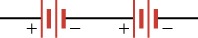
What circuit element is represented in the figure below?
- a battery
- a resistor
- a capacitor
- an inductor