Chapter Review
Concept Items
19.1 Ohm's Law
- The electrons flow from the negative terminal of the battery to the positive terminal of the battery.
- The electrons flow from the positive terminal of the battery to the negative terminal of the battery.
- Current is directly proportional to the resistance.
- Current is inversely proportional to the resistance.
- Current is proportional to the square of the resistance.
- Current is inversely proportional to the square of the resistance.
- Resistance is the property of materials to resist the passage of voltage.
- Resistance is the property of materials to resist the passage of electric current.
- Resistance is the property of materials to increase the passage of voltage.
- Resistance is the property of materials to increase the passage of electric current.
An accelerator accelerates He nuclei (change = 2e) to a speed of v = 2 × 10⁶ m/s. What is the current if the linear density of He nuclei is λ = 108 m–1?
- I = 9.6 × 10⁻⁵ A
- I = 3.2 × 10⁻⁵ A
- I = 12.8 × 10⁻⁵ A
- I = 6.4 × 10⁻⁵ A
- Make a resistor from this material and measure the current going through this resistor for several different voltages. If the current is proportional to the voltage, then the material is ohmic.
- Make a resistor from this material and measure the current going through this resistor for several different voltages. If the current is inversely proportional to the voltage, then the material is ohmic.
- Make a resistor from this material and measure the current going through this resistor for several different voltages. If the current is proportional to the square of the voltage, then the material is ohmic.
- Make a resistor from this material and measure the current going through this resistor for several different voltages. If the current is inversely proportional to the square of the voltage, then the material is ohmic.
What voltage is needed to make 6 C of charge traverse a 100-Ω resistor in 1 min?
- The required voltage is 1 × 10⁻³ V.
- The required voltage is 10 V.
- The required voltage is 1,000 V.
- The required voltage is 10,000 V.
Resistors typically obey Ohm’s law at low currents, but show deviations at higher currents because of heating. Suppose you were to conduct an experiment measuring the voltage, V, across a resistor as a function of current, I, including currents whose deviations from Ohm’s law start to become apparent. For a data plot of V versus I, which of the following functions would be best to fit the data? Assume that a, b, and c are nonzero constants adjusted to fit the data.
19.2 Series Circuits
In which circuit are all the resistors connected in series?

- 0 V, 0 A
- 0 V, 10 A
- 10 V, 0 A
- 10 V, 10 A
19.3 Parallel Circuits
- No, because for parallel combination of resistors, the resistance through the remaining circuit increases.
- Yes, because for parallel combination of resistors, the resistance through the remaining circuit increases.
- Adding resistors in parallel gives the current a shorter path through which it can flow hence decreases the overall resistance.
- Adding resistors in parallel gives the current another path through which it can flow hence decreases the overall resistance.
- Adding resistors in parallel reduce the number of paths through which the current can flow hence decreases the overall resistance.
- Adding resistors in parallel gives the current longer path through which it can flow hence decreases the overall resistance.
19.4 Electric Power
To draw the most power from a battery, should you connect a small or a large resistance across its terminals? Explain.
- Small resistance, because smaller resistance will lead to the largest power
- Large resistance, because smaller resistance will lead to the largest power
If you double the current through a resistor, by what factor does the power dissipated by the resistor change?
- Power increases by a factor of two.
- Power increases by a factor of four.
- Power increases by a factor of eight.
- Power increases by a factor of 16.
Critical Thinking Items
19.2 Series Circuits
Given three batteries (5V, 9V, 12V) and five resistors (10, 20, 30, 40, 50Ω) to choose from, what can you choose to form a circuit diagram with a current of 0.175A? You do not need to use all of the components.
- Batteries (5V, 9V) and resistors (30Ω, 50Ω) connected in series
- Batteries (5V4, 12V) and resistors (10Ω, 20Ω, 40Ω, and 50Ω) connected in series.
- Batteries (5V, 9V, and 12V) and resistors (10Ω, 20Ω, and 30Ω) connected in series.
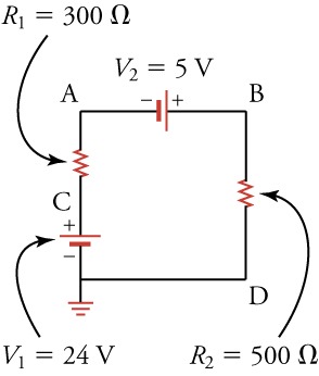
- A, B, C, D
- B, C, A, D
- C, B, A, D
- D, A, B, C
19.3 Parallel Circuits
- No, all practical resistor circuits cannot be reduced to series and parallel combinations.
- Yes, all practical resistor circuits can be reduced to series and parallel combinations.
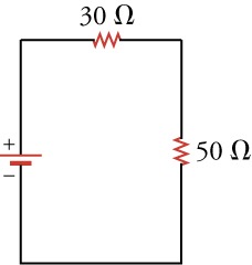
What is the equivalent resistance of the circuit shown below?

- The equivalent resistance of the circuit 14 Ω.
- The equivalent resistance of the circuit 16.7 Ω.
- The equivalent resistance of the circuit 140 Ω.
- The equivalent resistance of the circuit 195 Ω.
19.4 Electric Power
Two lamps have different resistances. (a) If the lamps are connected in parallel, which one is brighter, the lamp with greater resistance or the lamp with less resistance? (b) If the lamps are connected in series, which one is brighter? Note that the brighter lamp dissipates more power.
- (a) lamp with greater resistance; (b) lamp with less resistance
- (a) lamp with greater resistance; (b) lamp with greater resistance
- (a) lamp with less resistance; (b) lamp with less resistance
- (a) lamp with less resistance; (b) lamp with greater resistance
To measure the power consumed by your laptop computer, you place an ammeter (a device that measures electric current) in series with its DC power supply. When the screen is off, the computer draws 0.40 A of current.
When the screen is on at full brightness, it draws 0.90 A of current. Knowing the DC power supply delivers 16 V , how much power is used by the screen?
- The power used by the screen is −8.0 W.
- The power used by the screen is 0.3 W.
- The power used by the screen is 3.2 W.
- The power used by the screen is 8.0 W.
Problems
19.2 Series Circuits
What is the voltage drop across two 80-Ω resistors connected in series with 0.15 A flowing through them?
- 12 V
- 24 V
- 36 V
- 48 V
19.3 Parallel Circuits

- The equivalent resistance of the circuit is 32.7 Ω.
- The equivalent resistance of the circuit is 100 Ω.
- The equivalent resistance of the circuit is 327 Ω.
- The equivalent resistance of the circuit is 450 Ω.
- The equivalent resistance is 25 Ω.
- The equivalent resistance is 50 Ω.
- The equivalent resistance is 75 Ω.
- The equivalent resistance is 100 Ω.
19.4 Electric Power
When 12 V are applied across a resistor, it dissipates 120 W of power. What is the current through the resistor?
- The current is 1,440 A.
- The current is 10 A.
- The current is 0.1 A.
- The current is 0.01 A.
Warming 1 g of water requires 1 J of energy per . How long would it take to warm 1 L of water from 20 to 40 °C if you immerse in the water a 1-kW resistor connected across a 9.0-V batteries aligned in series?
- 10 min
- 20 min
- 30 min
- 40 min
Performance Task
19.4 Electric Power
- An incandescent light bulb (i.e., and old-fashioned light bulb with a little wire in it)
- A lightbulb socket to hold the light bulb
- A variable voltage source
- An ammeter
- Screw the lightbulb into its socket. Connect the positive terminal of the voltage source to the input of the ammeter. Connect the output of the ammeter to one connection of the socket. Connect the other connection of the socket to the negative terminal of the voltage source. Ensure that the voltage source is set to supply DC voltage and that the ammeter is set to measure DC amperes. The desired circuit is shown below.

- On a piece of paper, make a two-column table with 10 rows. Label the left column volts and the right column current. Adjust the voltage source so that it supplies from between 1 and 10 volts DC. For each voltage, write the voltage in the volts column and the corresponding amperage measured by the ammeter in the current column. Make a plot of volts versus current, that is, a plot with volts on the vertical axis and current on the horizontal axis. Use this data and the plot to answer the following questions:
- What is the resistance of the lightbulb?
- What is the range of possible error in your result for the resistance?
- In a single word, how would you describe the curve formed by the data points?